


SHMS busways are designed for making electrical connections of power equipment at electrical stations and substations, in residential buildings, retail facilities, agricultural and industrial sites, and are installed in three-phase AC circuits with a frequency of 50 and 60 Hz, nominal voltage up to 1 kV and nominal current up to 11,000 A, and in DC circuits with voltage up to 1.5 kV and nominal current up to 22,800 A.
SHMS busbars
«sandwich» type

Rated current
up to 6 710 A

Rated voltage
up to 1 kV

Protection rating
IP55

Operating conditions
-45°...+60°С
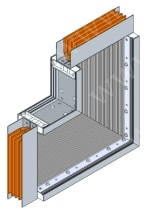
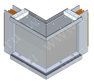
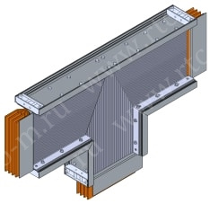
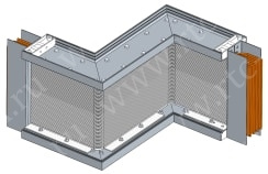


Details
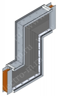
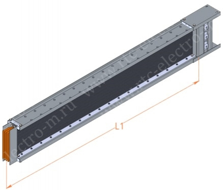
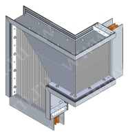
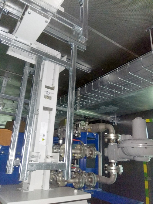
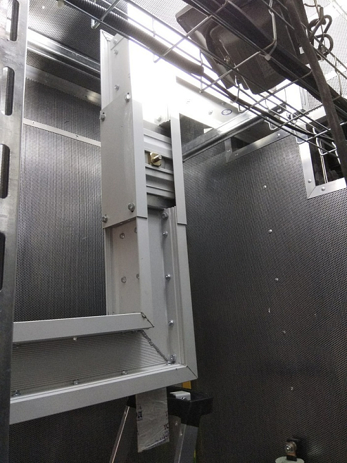
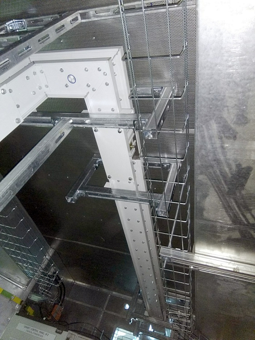
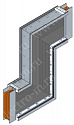
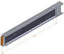
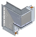
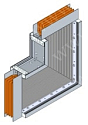
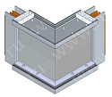
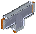
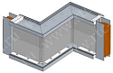
The SHMS busway consists of sections of various configurations. A busway section (Fig. 1) consists of parallel copper or aluminum insulated rectangular conductors enclosed in an extruded aluminum housing with cooling fins. The absence of air gaps between the conductors reduces inductive resistance and improves the system's heat dissipation. Busway sections are manufactured with a maximum length of 4 meters.
In the SHMS busway, all conductors are insulated with Mylar film. The insulation has high chemical resistance, is non-flammable, provides excellent electrical insulation, and protects the conductors from moisture and air contact. The joint design of the busway sections allows compensation for construction tolerances.

Fig. 1. SHMS Busway Sections
Sections are joined together (Fig. 2) using a special set of connecting plates and insulating partitions fastened with screws (for a more detailed description of the joining process, see the catalog on p. 55).

Fig. 2. SHMS Busway Section Connection
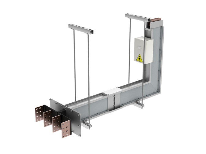
For connection to various electrical equipment, special so-called terminal sections are manufactured (see Fig. 3). Terminal sections can be made in different configurations depending on project requirements. The contacts of terminal sections have holes for bolted connection to electrical equipment (for more detailed description, see catalog pp. 48–50). For connecting busway sections to each other, no holes in the contacts are required.

Fig. 3. SHMS Busway Terminal Sections
To compensate for thermal expansion of the busway, special "compensation sections" are used (see Fig. 4). The average installation interval is 40 meters for busways with copper conductors and 35 meters for busways with aluminum conductors. The exact placement is determined according to the specific route configuration of the project.

Fig. 4. SHMS Busway Compensation Section
The busway can additionally be equipped with cabinets containing current and voltage transformers, branch devices for cable connections, and protective covers with busbars and compensators for connecting the busway to the outputs of transformers and low-voltage switchgear cabinets (LVSG). The list of busway components is determined by the assembly drawing of the route developed for the specific facility. Upon customer request, the busway contacts can be coated with tin, nickel, or silver.
The busway delivery set includes:
- busway sections;
- set of connecting plates for joining sections;
- busbar compensators for equipment connection;
- busway mounting system to building structures and fasteners;
- grounding system for supports, plates, protective covers, etc.
The accompanying documentation includes:
- passport;
- operation manual;
- installation instructions;
- design documentation;
- packing list;
- acceptance test reports;
- warranty certificate.


